

Discussion on Regulatory Blind Spots of IEC 61000-4-6 Conducted Susceptibility (C.S.)
In the IEC 61000-4-6 CS test, test voltage strength levels such as 1V / 3V / 10V are defined. However, whether these voltage levels—i.e., immunity test voltages—are referenced at the "source" of the generator or at the input of the CDN (after the 6dB attenuator) is unclear. Both interpretations are reflected in the regulatory diagrams, leading to confusion. Here, we clarify and share insights to help EMC colleagues establish a correct understanding. It is recommended that this regulatory ambiguity be proposed for amendment at the annual IEC meetings.
Immunity Strength Requirements and Corresponding Voltage U₀ Table 1 below shows the immunity strength levels and corresponding voltages (U₀). In the standard, some diagrams mark the voltage U₀ at the generator's source, while others define it before the 6dB attenuator (as shown in Figures 1 and 2). This leads to a potential twofold discrepancy in the immunity test voltage.
Table 1
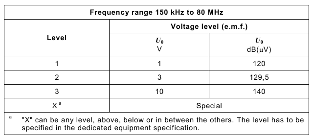
Figure 1
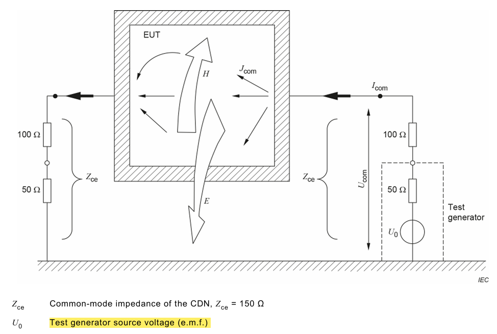
Figure 2
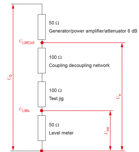
In Figure 2, markings similarly mislead engineers into thinking U₀ refers to the voltage before the 6dB attenuator.
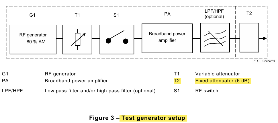
On the other hand, some regulatory diagrams define U₀ after the 6dB attenuator, such as Figure 3 and Figure 4(Here T2 represents the 6dB attenuator.)
Figure 3
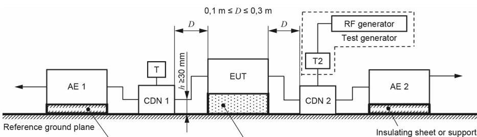
Figure 4
Interpretation of the Regulation Text and Conclusion
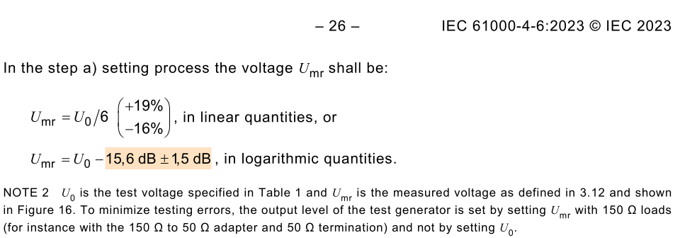
Analyzing the regulation text and formulas shown below, it is evident that the immunity test voltage is defined after the 6dB attenuator (because the formulas do not account for the 6dB attenuator). The 6dB attenuator is included in the test setup mainly to prevent damage to the generator from reflected waves. You can use a 6dB or even a 3dB attenuator:
Laboratory Validation Method
1. Directly select the internal calibration file for 150kHz/10V output (set to unmodulated mode), and measure the 150kHz VRMS using an oscilloscope before the 6dB attenuator to quickly confirm the source voltage. (If U₀ is 10 VRMS, you should measure 20 VRMS here.)
2. The standard voltage at this point should be 20 VRMS (±1.5dB).
3. Then select the internal calibration file for 200kHz/10V output (still unmodulated mode) and again measure the 200kHz VRMS before the 6dB attenuator. The voltage should still be 20 VRMS (±1.5dB).
4. Subsequently, you can verify measurements after the 6dB attenuator and after the CDN to understand the characteristics of both.
5. The same principle applies when using spectrum analyzers for measurement.
Relevant information

EU Releases Exemption Guidelines on Removability and Replaceability of Portable and LMT Batteries — Multiple Product Categories Relief Granted
On July 14, 2026, the European Commission published the "Commission Guidelines to Facilitate the Harmonised Application of Provisions on the Removability and Replaceability of Portable and Light Means of Transport (LMT) Batteries" (Commission Notice C(2026) 5032 final). These guidelines aim to provide a uniform interpretative framework for the implementation of Article 11 of the EU Battery Regulat

6G Developments: Past, Present and Future
The formulation of 6G standards has entered a more concrete phase. At the 3GPP RAN Plenary Meeting held in Singapore in June 2026, the industry made progress in multiple key research areas and finalized the timeline for Release 21, which is regarded as the first standard version expected to formally define 6G.

Overview of EN IEC 61000-4-29:2026
The key focus of the 2026 edition is to address new DC power distribution environments, especially higher-voltage DC systems. It also clarifies test generator capability, duration tolerance, current limitation during short interruptions, inrush current verification, result evaluation, and test report requirements. For products using 24 Vdc, 48 Vdc, 380 Vdc, 400 Vdc, 800 Vdc, or other DC input pow