

Latent Cognitive Risks in EMC Compliance Testing for AI-Based Power Systems
1. Introduction
Amid the rapid evolution of AI servers and high-power electrical modules, the demand for electrical energy continues to surge. As power control scales up, design instability increases accordingly—manifesting in challenges such as thermal effects, structural safety and spacing constraints, component selection, feedback response speed, and surge currents. Achieving stable and reliable products under these conditions presents a formidable engineering challenge.
Currently, the development of high-power energy products is outpacing regulatory frameworks, which struggle to keep up with the speed of innovation. This paper focuses specifically on the conduction emission (CE) aspect of EMC testing, exploring the latent risks that may arise from conventional setups and parameter compensation strategies—risks that often remain hidden yet carry significant implications for product reliability.
2. Explanation of Cognitive Risks
In typical EMC laboratories, all instruments and equipment in use undergo calibration. Once calibration parameters are obtained, low-frequency attenuation is often compensated during testing. While this approach may appear reasonable for low-power products, it introduces significant blind spots when applied to high-power systems—particularly in conduction emission (CE) testing. One such blind spot arises from relying solely on LISN (Line-Impedance Stabilization Network) attenuation compensation. The risks associated with this approach are outlined below:
(1) According to CE testing regulations, the setup must include power delivery through a LISN. The LISN serves two primary functions:
First, it ensures impedance matching between the equipment under test and the measurement system.
Second, it blocks external noise from entering the system, which could distort measurement results. Additionally, the LISN prevents internal noise from the product from leaking outward, which could falsely suggest that the product is operating normally when, in fact, it is not.
A suitable additional radio-frequency filter “may be” inserted between the AMN and the mains supply the filter .There is not shown in the test diagram, which can be misleading.
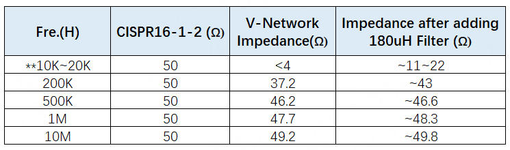
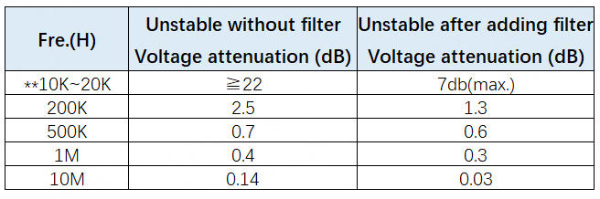
(2) If the product exhibits an abnormality under a certain load, such as a resonance, the LISN exhibits low impedance at low frequencies. Without a filter, this resonance may be eliminated immediately, and the product may pass the test, but the cause of the resonance will still exist (see Table 1). If a filter is added to the power output before connecting it to the LISN, the instability will not be affected by the LISN (see Table 2). Furthermore, high-power circuit design generally considers the range of impedance values before and after the product (e.g., filters) to avoid resonance issues.
Table 1(Refer to CISPR 16-1-2)
Based on the current high-power filter and CDN inductor designs on the market, the following are the ranges of common inductance values:
100uH ~ 1mH
The larger the inductance value, the better the noise suppression capability. However, the design needs to be matched with the system requirements to avoid affecting the response speed.
Table 2
3. Exploration of Feasible Approaches
To ensure consistent quality across design, verification testing, and real-world application, and to avoid latent oversights, this section proposes several key considerations that laboratories should take into account. These supporting details are currently not addressed in existing standards, yet they play a critical role in enhancing the reliability and accuracy of EMC testing for high-power AI-based electrical products.
(1) In CE testing setups, it is recommended to add a filter before the LISN to prevent low-frequency impedance from becoming excessively low, which may lead to misinterpretation of test results. For the filter design, an inductance value between 150?μH and 180?μH is suggested.
(2) High-power products typically exhibit significant inrush current. Therefore, the product should incorporate a soft-start function, or the test procedure should adopt a gradual loading approach. Additionally, the inclusion of a filter can help suppress interference caused by surge currents.
(3) The design of high-power products must account for the input/output impedance as seen from the external interface. To ensure consistency and interoperability, it is advisable to establish unified reference standards across different power layers. This enables the development of modular products with shared compatibility and design coherence.
4. Conclusion
From the above analysis, it can be seen that in actual use, large-scale power products need to consider the safety design of each block, such as the importance of the filter mentioned above. In addition, in the future, it is necessary to establish parameters for each block, provide design references, and establish a consistency benchmark so that the subsequent development of such products can meet the commonality and shared modular architecture, and more importantly, save resources.
Relevant information

EU Releases Exemption Guidelines on Removability and Replaceability of Portable and LMT Batteries — Multiple Product Categories Relief Granted
On July 14, 2026, the European Commission published the "Commission Guidelines to Facilitate the Harmonised Application of Provisions on the Removability and Replaceability of Portable and Light Means of Transport (LMT) Batteries" (Commission Notice C(2026) 5032 final). These guidelines aim to provide a uniform interpretative framework for the implementation of Article 11 of the EU Battery Regulat

6G Developments: Past, Present and Future
The formulation of 6G standards has entered a more concrete phase. At the 3GPP RAN Plenary Meeting held in Singapore in June 2026, the industry made progress in multiple key research areas and finalized the timeline for Release 21, which is regarded as the first standard version expected to formally define 6G.

Overview of EN IEC 61000-4-29:2026
The key focus of the 2026 edition is to address new DC power distribution environments, especially higher-voltage DC systems. It also clarifies test generator capability, duration tolerance, current limitation during short interruptions, inrush current verification, result evaluation, and test report requirements. For products using 24 Vdc, 48 Vdc, 380 Vdc, 400 Vdc, 800 Vdc, or other DC input pow