

1. Introduction
Currently, there is no dedicated international product standard specifically governing EMC testing for AI data centers. Instead, verification procedures still rely on familiar frameworks such as CISPR 32, CISPR 35, and harmonic requirements. However, the unique characteristics of AI data centers present new challenges: high-power three-phase electrical systems, ultra-high-speed and high-volume data streaming, advanced thermal dissipation technologies, substantial system loading, and complex power distribution architectures. The frequency spectrum involved spans from low-frequency control of three-phase power stability to coupling effects and high-frequency scattering induced by ultra-fast data transmission. These factors collectively pose significant tests and challenges to EMC validation in this emerging domain.
2. Perspective and Considerations
2.1 Three-Phase Power PSU Rack
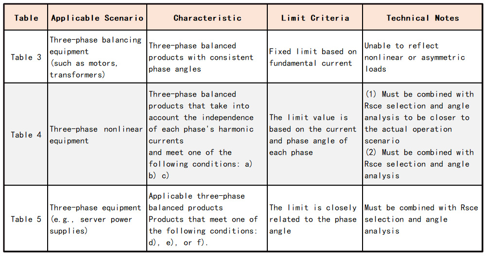
(1) The IEC 61000-3-12 standard, applicable to equipment drawing more than 16A per phase, specifies harmonic current limits for three-phase systems. Depending on the product’s operational characteristics, compliance testing can be conducted using Table 3 through Table 5 of the standard. This section provides an analysis of the differences among these tables and offers guidance on how to select the appropriate test criteria based on product behavior and system configuration.
(1.1) Practical Implementation Considerations
For server products, the ideal approach is to perform testing using Table 3 with Rsce = 33. However, due to the complexity of these products—especially when power exceeds 60 kW—it is often difficult to meet the linearity requirements. If Rsce = 33 cannot be satisfied, alternative values such as 66, 120, or 250 may be considered. In such cases, it is necessary to report the selected Rsce value to the CSP (Certification Service Provider) for approval, and clearly annotate the chosen Rsce in the test report.
For systems utilizing dual power sources combined into a high-voltage output, or those incorporating CDU (Coolant Distribution Unit) equipment, Table 4 is generally more representative of actual operating conditions. During the development phase, it is essential to measure the relationship between current and voltage phase angles, aiming to meet the angular criteria defined in Table 4. This data supports the CSP in calculating harmonic current superposition and assessing temperature rise in protective switching devices.
(1.2) Key Considerations
When applying Table 4, if the phase angle between the fifth harmonic current (I5) and the fundamental voltage is controlled within the range of 90° to 150°, the product input tends to exhibit capacitive characteristics. Under such conditions, transient current levels may increase significantly. Therefore, it is recommended to incorporate filters operating above 150 kHz to mitigate potential EMC risks and ensure system stability.
(1.3) Recommended EMC Verification Procedure (for Servers or PSUs Above 60 kW)
a. Configure Table 4 with Rsce = 33. After a 10-minute warm-up period, begin testing for 20 minutes. Perform measurements at 10%, 20%, 50%, and 100% load levels. Examine the phase angle between the fifth harmonic current (I5) and the fundamental voltage to determine whether it falls within the 90°–150° range or varies randomly across 0°–360°. Record all observations and proceed to step b.
b. If the measured angles fall within the criteria defined in step a, initiate a second formal test using Table 4 with Rsce = 33. If the test passes, the verification is complete. If the test fails to meet the limit criteria, proceed to step c.
c. Reconfigure the test using Table 4 with Rsce = 250 and conduct a third round of testing. If the test passes, the verification is complete.
d. If the phase angle criteria in step a are not met, proceed to step e.
e. Switch to Table 3 and determine an appropriate Rsce value based on the results from step b. Consider Rsce values such as 66, 120, 250, or 350, and conduct the test accordingly.
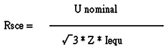
The Z value typically includes the combined impedance of the transformer, busbar, and cable. (The laboratory cannot determine the Z value in the above formula.) Therefore, the selection of Rsce should be recommended by the CSP. Furthermore, the Rsce value also involves the characteristic parameters of the power supply and circuit breaker.
2.2 Potential Oversights in CE (Conducted Emission) Testing for PSUs
Under certain load conditions, a product may exhibit abnormal low-frequency resonance. In such cases, the LISN (Line Impedance Stabilization Network) presents low impedance at low frequencies. If no filter is installed at the LISN input, this resonance may be inadvertently discharged to ground, potentially leading to a false pass in the CE test. However, the root cause of the resonance remains unresolved.
By inserting a filter between the power source output and the LISN, the instability is no longer masked by the LISN’s low-frequency characteristics. Furthermore, in high-power circuit designs, it is essential to consider the impedance range before and after the product—such as the inclusion of filters—to prevent resonance issues.
For a detailed discussion of this topic, refer to BTL’s publication: 'Latent Cognitive Risks in EMC Compliance Testing for AI-Based Power Systems'
2.3 IEC 61000-3-11: Voltage Flicker Considerations
The original intent of voltage flicker limits under IEC 61000-3-11 was to regulate power products that could cause flicker disturbances—particularly affecting shared power sources, other connected devices, or lighting systems. However, modern AI systems typically operate within dedicated power zones equipped with their own voltage regulation and protection infrastructure. These systems feature isolated and robust power management architectures. As such, the applicability of flicker requirements to AI systems is limited and may no longer be relevant under current deployment models.
2.4 Recommendation: Include Handheld Communication Immunity Testing
During operations or inspections within computer rooms or AI Data Centers, personnel often carry handheld radios, mobile phones, or use video recording devices. These wireless communication tools may introduce electromagnetic interference (EMI) to nearby equipment. Therefore, it is advisable to incorporate handheld device immunity testing into the EMC verification process.
This consideration is especially relevant for environments such as railway system control rooms, where similar testing protocols are already applied. For applicable test methods and regulatory references, ISO 11452-9 provides a suitable framework for evaluating immunity against radiated disturbances from portable transmitters.
2.5 Recommendation: Adopt EV-Grade Shielded Cables for AI Server PSUs
Currently, external PSU cables used in AI servers often lack multi-layer mesh shielding, which makes them vulnerable to radiated emissions (RE) and complicates system design and stability—particularly in terms of impedance weighting and noise control.
In contrast, electric vehicles (EVs) have long adopted shielded cable architectures with mature design practices. These cables offer effective electromagnetic shielding, with noise suppression capabilities reaching 40 dB to 60 dB. By adopting similar cable types for AI server PSUs, RE scattering can be significantly reduced, enhancing both EMC performance and overall system robustness.
3. Conclusion
As the performance demands of AI servers continue to grow, EMC verification must evolve in tandem—requiring holistic, system-wide design alignment and weight-balanced development strategies. Beyond technical compliance, it is equally important to reflect on environmental limitations and continuously refine design practices to enhance product manufacturability, consistency, and stability.
In this domain, especially for high-power products, there remains significant room for advancement in certification methodologies, as outlined in this paper. Furthermore, cross-disciplinary integration and mutual learning between fields should be actively encouraged to foster innovation and resilience across the ecosystem.
Relevant information

EU Releases Exemption Guidelines on Removability and Replaceability of Portable and LMT Batteries — Multiple Product Categories Relief Granted
On July 14, 2026, the European Commission published the "Commission Guidelines to Facilitate the Harmonised Application of Provisions on the Removability and Replaceability of Portable and Light Means of Transport (LMT) Batteries" (Commission Notice C(2026) 5032 final). These guidelines aim to provide a uniform interpretative framework for the implementation of Article 11 of the EU Battery Regulat

6G Developments: Past, Present and Future
The formulation of 6G standards has entered a more concrete phase. At the 3GPP RAN Plenary Meeting held in Singapore in June 2026, the industry made progress in multiple key research areas and finalized the timeline for Release 21, which is regarded as the first standard version expected to formally define 6G.

Overview of EN IEC 61000-4-29:2026
The key focus of the 2026 edition is to address new DC power distribution environments, especially higher-voltage DC systems. It also clarifies test generator capability, duration tolerance, current limitation during short interruptions, inrush current verification, result evaluation, and test report requirements. For products using 24 Vdc, 48 Vdc, 380 Vdc, 400 Vdc, 800 Vdc, or other DC input pow