

Television sets fail to meet ETSI EN 303 340 testing standards and their export to the EU is blocked
Digital TV sets, set-top boxes and other products are exported to the European Union. Everyone should be quite familiar with the need to meet multimedia product standards such as EN 55032 and EN 55035. For instance, receiver products equipped with external antenna input (tuner) ports and capable of receiving DVB-T and/or DVB-T2 signals for terrestrial digital TV broadcasting, The ETSI EN 303 340 standard still needs to be implemented. Otherwise, there will still be problems of blocked product exports to the European Union, resulting in various losses. The following introduces the test items and key requirements of this standard.
Note: Not applicable to receivers without external antenna connectors, diversity receivers, and receiver products used for mobile or vehicle-mounted reception.
Test item:
No | Description | Essential requirements of Directive | Clause(s) of the present document |
| 1 | Receiver sensitivity | 3.2 | 4.2.3 |
| 2 | Receiver adjacent channel selectivity | 3.2 | 4.2.4 |
| 3 | Receiver blocking | 3.2 | 4.2.5 |
| 4 | Receiver overloading | 3.2 | 4.2.6 |
Broadcasting working frequency band:
VHF Very High Frequency 30-300MHz | Band III 167-223MHz |
UHF Ultra High Frequency 300-1000MHz | Band IV 447-566MH |
Band V 606-958MHz |
Test project definition:
Receiver sensitivity:The maximum available sensitivity is defined as the minimum receiver radio frequency (RF) input signal level or field strength that can generate the specified analog signal ratio (SINAD) or bit error rate (BER), or other specified output performance depending on the input signal level. The sensitivity of the receiver is determined by the deterioration of the image at the beginning;
Receiver adjacent channel selectivity:adjacent channel selectivity (I/C) is defined as the measure of the capability of the receiver to receive a wanted modulated signal without exceeding a given degradation due to the presence of an unwanted signal which differs in frequency from the wanted signal by an amount equal to the adjacent channel separation for which the equipment is intended. In the present document adjacent channel selectivity is determined by the onset of picture degradation.
Receiver blocking:The measure of the capability of the receiver to receive a wanted modulated signal without exceeding a given degradation due to the presence of an unwanted signal at any frequency other than those of the spurious responses or of the adjacent channels. In the present document receiver blocking is determined by the onset of picture degradation.
Receiver overloading:Overloading is the interfering signal level expressed in dBm, above which the receiver begins to lose its ability to discriminate against interfering signals at frequencies differing from that of the wanted signal due to the onset of strong non-linear behaviour. In the present document the overload level is determined by the onset of picture degradation.
onset of picture degradation:minimum time between successive errors in the displayed video is 15 seconds.
Next, we will focus on introducing the receiver sensitivity test to you. If you are also interested in other test items, please feel free to consult the BTL General Electronics Division team at any time.
Setup for receiver sensitivity testing
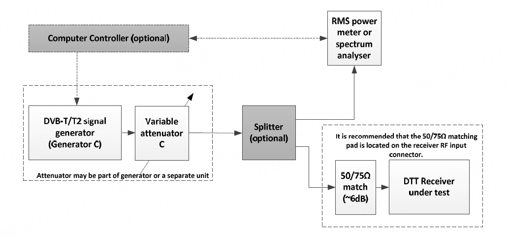
Receiver sensitivity test steps
a. Set the useful signal generated by signal generator C to the useful signal frequency shown in the following table and configure the corresponding DTT mode parameters;
b. Determine the attenuation of the cable, splitter, and 50/75 ohm matching pad;
c. Set the useful signal C level at the tuner port of the broadcast receiver to -50 DBM and record the value of "attenuator C" (=AC1);
d. Tune the DTT receiver to the useful channel;
e. Increase the attenuation of "attenuator C" until the image completely disappears;
f. Gradually reduce the attenuation of "attenuator C" until the image begins to deteriorate. Force the tested receiver to re-capture the signal and readjust the "attenuator C" until the image begins to deteriorate. Record the attenuator setting value (=AC2):
g. The receiver sensitivity shall be recorded in the measurement record sheet according to the following formula: Sensitivity = -50 - (AC2 - AC1) dBm;
h. Repeat steps a) to g) for the remaining frequencies in the table below。
Receiver sensitivity requirements
Test Number | Test Hescription | center frequency of the wanted signal (MHz) | Required sensitivity limit for DTT configurations in tables 2 and 3 (dBm) | |
DVB-T | DVB-T2 | |||
| 1 | Sensitivity VHF | 198.5 | -77 | -75 |
| 2 | Sensitivity UHF | 666 | -77 | -75 |
BTL has many years of relevant execution experience in digital TVS, set-top boxes and other multimedia devices. We have helped many well-known brands sell to overseas countries such as the European Union. We have a professional multimedia product line team in charge.
Relevant information

EU Releases Exemption Guidelines on Removability and Replaceability of Portable and LMT Batteries — Multiple Product Categories Relief Granted
On July 14, 2026, the European Commission published the "Commission Guidelines to Facilitate the Harmonised Application of Provisions on the Removability and Replaceability of Portable and Light Means of Transport (LMT) Batteries" (Commission Notice C(2026) 5032 final). These guidelines aim to provide a uniform interpretative framework for the implementation of Article 11 of the EU Battery Regulat

6G Developments: Past, Present and Future
The formulation of 6G standards has entered a more concrete phase. At the 3GPP RAN Plenary Meeting held in Singapore in June 2026, the industry made progress in multiple key research areas and finalized the timeline for Release 21, which is regarded as the first standard version expected to formally define 6G.

Overview of EN IEC 61000-4-29:2026
The key focus of the 2026 edition is to address new DC power distribution environments, especially higher-voltage DC systems. It also clarifies test generator capability, duration tolerance, current limitation during short interruptions, inrush current verification, result evaluation, and test report requirements. For products using 24 Vdc, 48 Vdc, 380 Vdc, 400 Vdc, 800 Vdc, or other DC input pow